The following information is from a class given by Jim Hinnant on Field Day 2026, June 27, 2026.
Amateur Radio Grounding and Bonding Procedures
Proper grounding and bonding are essential parts of a safe and reliable amateur radio station. A well-designed system helps protect people from electrical shock, reduces equipment damage, minimizes unwanted RF in the shack, and provides a controlled path for lightning and surge energy.
No residential grounding system can guarantee complete protection from a direct lightning strike. However, proper grounding, bonding, surge protection, cable routing, and equipment-disconnection procedures can substantially reduce the risk of injury and equipment damage.
This article is based on the revised Amateur Radio Grounding Procedures training presentation and uses the 2023 National Electrical Code with North Carolina amendments, commonly referred to as the 2023 North Carolina Electrical Code, as its code framework. The 2023 State Electrical Code amendments were accepted by the North Carolina Building Code Council and the Rules Review Commission. Always confirm the requirements for a particular installation with the local authority having jurisdiction.
About the Author
Jim Hinnant, KR4BMI, has more than 46 years of experience with commercial television and computer systems. He obtained his 1st Class Radiotelephone License from the FCC in 1980 which was later converted to a General Radiotelephone License when the FCC phased out the class license sytem. He also holds a Bachelor of Science Degree in Broadcast Engineering with a minor in Computer Science and has taught for Wayne Community College and NC Wesleyan College. He currently is Owner/Manager of Xpress Communications in Goldsboro, NC.
Why Grounding and Bonding Matter
A properly designed amateur radio grounding and bonding system serves several purposes:
- Protects people from electrical shock
- Reduces the possibility of equipment damage
- Minimizes RF interference
- Provides a path for lightning-induced energy
- Improves station reliability
- Helps keep interconnected equipment at the same electrical potential
Grounding and bonding are related, but they are not the same.
Grounding
Grounding connects an electrical system or conductive object to the earth.
Examples include:
- Connecting a tower to ground rods
- Connecting an antenna mast to the grounding-electrode system
- Connecting a coaxial entrance panel to the station grounding system
Bonding
Bonding connects conductive objects together so that they remain at approximately the same electrical potential.
Examples include:
- Bonding radio ground rods to the house service ground
- Bonding tower ground rods together
- Bonding radios and power supplies to a common station ground bus
- Bonding the coax entrance panel to the building grounding-electrode system
Grounding connects equipment to earth. Bonding connects equipment and grounding systems together. Both are required for a complete safety system.
Electrical Safety Grounding

The electrical safety ground provides a low-impedance path for electrical fault current. It helps prevent exposed metal cabinets and chassis from remaining energized if an internal electrical fault occurs.
Station equipment powered from household electricity should be connected through properly grounded receptacles. The grounded conductor, commonly called the neutral, and the equipment-grounding conductor should normally be bonded together only at the service disconnect or another location specifically permitted by the electrical code.
Improper neutral-to-ground connections downstream of the service disconnect can place current on equipment grounding conductors and metal enclosures.
Important Electrical-Code Articles
Several portions of the 2023 NEC are particularly important to amateur radio installations.
Article 250 — Grounding and Bonding
Article 250 addresses matters such as:
- Grounding electrodes
- Ground rods
- Bonding of grounding electrodes
- Interconnection with the electrical-service ground
- Grounding-electrode conductor sizing
- Equipment grounding
- Bonding of conductive structures
One of the most important principles is that a radio ground rod must not remain isolated from the house electrical grounding system.
A separate radio ground rod may appear to provide additional protection, but an unbonded rod can create a dangerous voltage difference between the radio equipment and the building electrical system during a lightning event or electrical fault.
All grounding electrodes associated with the station should be properly bonded to the building grounding-electrode system.
Article 800 — Communications Circuits
Article 800 addresses communications wiring and related grounding and bonding requirements.
Among its purposes are:
- Bonding communications grounding conductors to the building grounding-electrode system
- Reducing voltage differences between communications and electrical systems
- Protecting exposed cables from abrasion, crushing, and physical damage
- Providing suitable protection where communications conductors enter a building
Network, telephone, control, and other communications cables can carry surge energy into a radio room just as coaxial cable can.
Article 810 — Radio and Television Equipment
Article 810 contains requirements applicable to radio and television receiving and transmitting equipment.
Depending on the installation, these requirements can include:
- Grounding the antenna mast
- Grounding the coaxial-cable shield
- Installing an antenna-discharge unit or surge protector
- Bonding the antenna grounding system to the building grounding-electrode system
- Routing antenna conductors away from electrical power conductors
- Keeping grounding conductors short and direct
10 AWG copper is the minimum grounding-conductor size for the covered application, but 6 AWG copper is recommended where practical for a more substantial installation.
Code minimums are not always the same as optimum lightning-performance practices. Larger conductors and wide copper strap can reduce impedance, particularly during fast-rising surge events.
2023 NEC Surge-Protection Requirements
Section 230.67 of the 2023 NEC addresses surge protection for electrical services supplying dwelling units.
A Type 1 or Type 2 surge-protective device, or SPD, is used to reduce electrical surges entering through the utility power system. Under the 2023 requirements , the SPD must have a nominal discharge-current rating of at least 10 kA.
A whole-house surge protector is an important layer of protection, but it does not replace:
- Coaxial surge protectors
- Tower and mast grounding
- Bonding of grounding electrodes
- Grounded cable-entry panels
- Control-line surge protectors
- Proper equipment-disconnection procedures
Surge protection should be treated as a coordinated system rather than a single device.
RF Grounding and Bonding
An RF ground helps control unwanted radio-frequency currents within the station.
Good RF bonding may:
- Reduce RF feedback
- Reduce RF on microphone cables
- Improve transmitted audio
- Reduce interference to computers and accessories
- Reduce RF burns from equipment cabinets
- Keep equipment at a common RF potential
At radio frequencies, a long round grounding wire may have considerable inductive reactance. A conductor that works adequately at 60 Hz may not provide an effective RF path.
For RF bonding:
- Keep connections short
- Avoid coils
- Avoid sharp bends
- Use wide copper strap where practical
- Bond equipment to a common ground bus
- Do not daisy-chain the ground connection through several pieces of equipment
The electrical safety ground must remain in place even when a separate RF bonding system is installed.
Understanding Lightning
Lightning can involve electrical activity traveling in both directions.
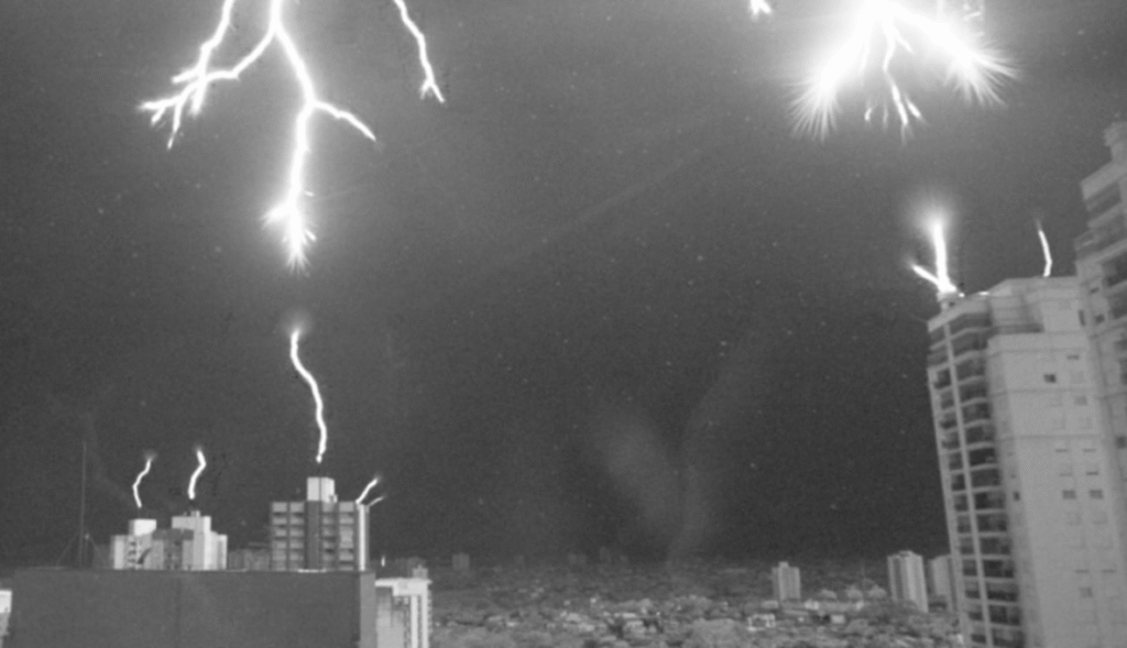
A typical cloud-to-ground event may include:
- A stepped leader traveling downward from a cloud
- Upward streamers rising from objects on the ground
- Connection of the ionized paths
- A powerful return stroke through the completed channel
This is why tall or pointed objects such as antennas, towers, trees, steeples, and masts may become involved in the development of a lightning path.
St. Elmo’s Fire
Before or during a thunderstorm, the electrical field between a cloud and the ground can become extremely intense.
The field becomes concentrated around sharp or elevated objects such as:
- Antenna tips
- Tower tops
- Sailboat masts
- Aircraft wings and propellers
- Church steeples
- Tree branches
When the field becomes strong enough, it can ionize the surrounding air and produce a visible glow known as St. Elmo’s fire.
A visible glow, buzzing, snapping, or corona discharge around an antenna or tower is a serious warning of an intense electrical field. Move away from the antenna system and seek safe shelter immediately.
Do not attempt to disconnect or ground cables after this activity has begun.
Direct and Nearby Lightning Strikes
Nothing can provide complete protection from every direct lightning strike. The purpose of a grounding and bonding system is to encourage lightning and surge current to remain outside the building and travel through an intended path.
Nearby strikes are also dangerous.
Lightning striking a nearby tree, power line, utility pole, or the ground can introduce damaging voltage through:
- Tree roots
- Wet soil
- Buried conductors
- Electrical wiring
- Coaxial cable
- Telephone lines
- Network cables
- Rotator wiring
- Antenna-control cables
Nearby lightning is a particular concern in Eastern North Carolina, where thunderstorms and strikes to trees are common.
The Faraday-Cage Principle
A Faraday cage is a conductive enclosure that directs electrical current around the protected area.
Examples can include:
- Automobiles
- Aircraft
- Metal buildings
- Shielded equipment rooms
Commercial radio and television transmitter sites often use extensive grounding grids. Conductors may be installed around walls, floors, ceilings, equipment racks, cable trays, and entry points. These wires do NOT make a complete loop giving us a single-point ground path. Commercial transmitter sites are now generally built to Motorola R56 standards. The “loop” has a break about opposite the common point ground buss bar with at least a 4 inch gap. Motorola R56 calls for a 2 AWG wire, but this may be considered overkill for private amateur shacks. NEC 2023 calls for 10 AWG, but 6 AWG wire may be a reachable compromise for most individuals.
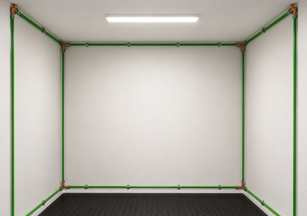
A residential radio room is rarely a complete Faraday cage, but the same principle supports the use of:
- Bonded metal entrance panels
- Grounded equipment racks
- Copper ground buses
- Short equipment bonds
- Bonded tower grounding
- Surge protection at every cable-entry point
The Single-Point Ground System
A single-point ground system brings the station’s grounding and bonding connections together at a common location.
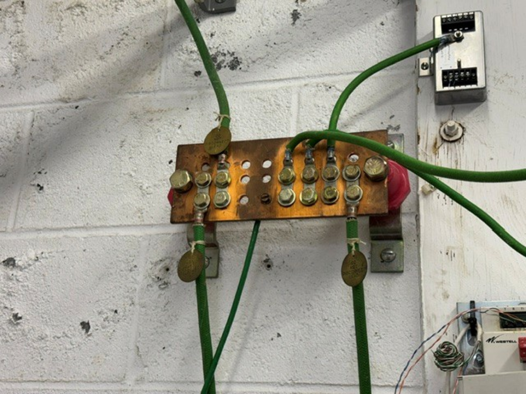
The objective is to minimize voltage differences between:
- Radio equipment
- AC safety grounds
- Coaxial-cable shields
- Tower structures
- Antenna masts
- Rotator cables
- Control wiring
- Communications lines
A typical installation may include:
- A metal coaxial-cable entrance panel
- Coaxial lightning arrestors mounted to the panel
- A grounding conductor or copper strap from the panel
- A station equipment ground bus
- A bond to the electrical-service grounding-electrode system
- Grounding and bonding conductors for the tower
- Surge protection for rotator, network, telephone, and control cables
Wide copper strap or 6 AWG or larger copper wire is commonly used where appropriate. Connections should be short, direct, and physically secure.
The term “single point” does not necessarily mean that only one ground rod is installed. It means that all station grounding systems are bonded together to function as one coordinated system.
Ground-Rod Installation
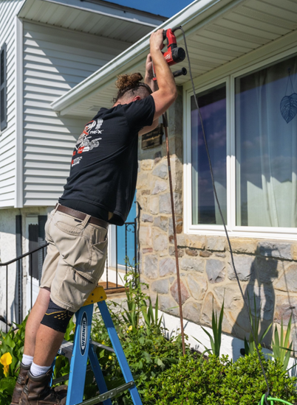

Recomendations are:
- Using listed 8-foot copper-clad rods
- Spacing rods approximately 6 to 16 feet apart
- Bonding all rods together
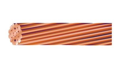
- Using 6 AWG or larger copper bonding conductors
- Keeping conductors short and straight
- Using listed grounding clamps
- Making secure physical connections
Greater separation between rods may improve their effectiveness when space and soil conditions permit.
Driving several rods without bonding them together does not create a safe grounding system. The rods must be bonded to each other and to the building grounding-electrode system.
Bonding the Tower
The tower base should be bonded to the grounding system.
Depending on the tower design, this may include:
- A ground rod near each tower leg
- Short conductors from the tower legs to the rods
- A perimeter bonding conductor
- A bond between the tower grounding system and the house service ground
- Listed connectors suitable for outdoor or direct-burial use
Paint, rust, oxidation, or galvanizing can prevent a reliable electrical connection. The connection point must provide clean metal-to-metal contact.
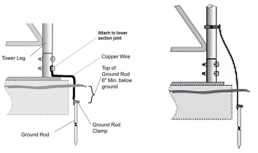
Only the area necessary for the connection should be prepared. The completed connection should then be protected from corrosion.
Bonding Coaxial-Cable Shields
Coaxial-cable shields should be grounded at the building entrance before the cables enter the shack.
This is commonly accomplished with:
- A metal bulkhead entrance panel
- Bulkhead feed-through connectors
- Coaxial lightning arrestors
- A short grounding conductor
- Copper strap
- Weatherproof cable fittings
The entrance panel should be bonded directly to the grounding system.
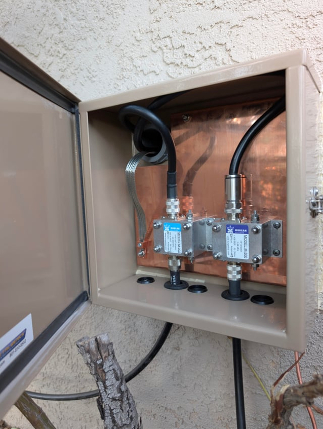
A lightning arrestor installed several feet inside the radio room allows surge current to enter the building before it reaches the arrestor. The protector should be placed at or immediately before the cable-entry point and NEVER inside.
Bonding Rotators and Metal Structures
Rotator housings, antenna support structures, equipment racks, and other conductive objects should be included in the bonding plan where appropriate.
Rotator and antenna-control cables can conduct lightning-induced voltage into the shack. Suitable multi-conductor surge protectors should be installed at the entrance when practical.
Every metallic conductor entering the building should be evaluated as a possible surge path.
Bonding Station Equipment
Install a common copper ground bus near the operating position.
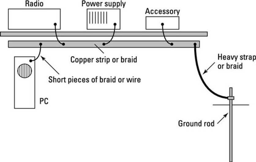
Equipment that may be bonded to the bus includes:
- Transceivers
- Amplifiers
- Antenna tuners
- Power supplies
- Computers
- Audio equipment
- Switches
- Test equipment
- Metal equipment racks
Each device should have its own short bond to the bus. Avoid grounding one radio through another radio’s cabinet.
The station bus must then be bonded to the overall station grounding system.
Coax Entrance Panels and Lightning Arrestors
The coax entrance panel is one of the most important elements of the station protection system.
A good entrance panel should:
- Be located near the cable-entry point
- Be made from conductive material
- Be directly bonded to the grounding system
- Hold properly rated coaxial arrestors
- Provide weather-resistant cable entry
- Permit cables to enter from the bottom where practical
- Include drip loops
- Keep the surge-current path outside the shack
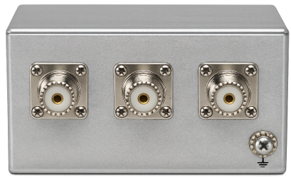
Lightning arrestors must be bonded to ground to operate properly. Merely placing an arrestor inline with the coax does not provide a complete surge path.
Disconnecting During Severe Storms
Disconnecting antennas and outside cables before a storm reaches the area provides an additional layer of protection.
Before severe weather arrives:
- Disconnect coaxial cables from radios and tuners.
- Disconnect rotator and external control cables where practical.
- Disconnect AC power from station equipment.
- Disconnect network and telephone cables where practical.
- Keep disconnected cables away from radios and other equipment.
- Ground or switch the disconnected coax through an appropriate external grounding arrangement.
A disconnected coax connector can still carry dangerous induced voltage. Laying it behind the radio does not make it safe.
Some operators place disconnected connectors in a glass jar or another insulating container. This may help prevent accidental contact or arcing to nearby objects, but the jar does not discharge lightning-induced voltage.
A better arrangement is an external grounding switch or disconnect system that bonds both the coaxial shield and center conductor to the grounded entrance panel while the station is not operating.
Grounding the disconnected coax can:
- Provide a path for induced voltage
- Equalize voltage
- Reduce static buildup
- Reduce the possibility of an arc near equipment
Never handle coaxial cables or attempt to disconnect a station while lightning is already nearby. Disconnect before the storm arrives.
Common Grounding Mistakes
Separate, unbonded ground rods
An isolated radio ground rod can create a dangerous voltage difference between the radio equipment and the electrical system.
Long or coiled grounding conductors
Coils, long conductors, sharp bends, and unnecessary turns increase impedance during a fast lightning surge.
Depending only on the AC outlet ground
The receptacle equipment-grounding conductor is essential for electrical safety, but it does not replace proper tower, mast, coax, and lightning grounding.
Installing arrestors inside the shack
Surge energy should be diverted at the cable entrance before it passes through the building.
Ignoring control and communications cables
Rotator, telephone, network, security, and remote-control cables can all carry surge energy.
Ignoring corrosion and water intrusion
A grounding connection that has become loose or corroded may not provide a dependable current path when it is needed.
Use Compatible Metals
Whenever practical, use similar and compatible metals together.
Examples include:
- Copper wire with copper-clad ground rods
- Copper conductors with listed bronze or copper clamps
- Listed transition connectors between copper and aluminum
Do not directly join copper to aluminum unless the connector is designed and listed for that combination.
Stainless-steel hardware is often useful for mechanical strength and corrosion resistance, but stainless steel is not the preferred primary electrical path. The intended electrical contact should be between clean copper or other compatible conductive surfaces.
Clean Contact Surfaces
Before making a bonding connection:
- Remove paint, rust, dirt, oxidation, or other contamination.
- Expose clean, bright metal.
- Install a suitable listed connector.
- Tighten the connection securely.
- Protect the finished connection from moisture.
When bonding to galvanized towers or structures, remove only enough coating to establish a reliable connection. Protect the prepared area after the bond is completed.
Use Antioxidant Compounds
Antioxidant compounds can help exclude moisture and oxygen from properly prepared electrical connections.
Products may include:
- No-Ox-ID
- Penetrox
- Ox-Gard
For copper-to-copper connections, the compound can help reduce weather-related corrosion.
For aluminum connections, an approved antioxidant compound is particularly important because aluminum quickly develops an oxide layer that can interfere with conductivity.
Antioxidant compound does not replace:
- Clean contact surfaces
- Proper mechanical pressure
- Compatible materials
- Listed connectors
Weatherproof Outdoor Coaxial Connections
A practical outdoor coax-weatherproofing procedure is:
- Tighten the connector correctly.
- Apply an appropriate protective compound to threaded metal surfaces where suitable.
- Apply an initial layer of high-quality electrical tape from the bottom upward.
- Cover it with self-amalgamating rubber tape or CoaxSeal.
- Add an outer layer of UV-resistant electrical tape.
- Form a drip loop below the connection.
- Support the cable so the connector is not carrying the cable’s weight.
- Bring exterior cables into entrance boxes from the bottom whenever possible.
Wrapping from the bottom upward causes each layer to overlap like roof shingles and helps shed water.
Protect Ground-Rod Connections
Ground-rod clamps should:
- Be listed for grounding use
- Be compatible with the rod and conductor
- Be rated for direct burial when buried
- Be tightened according to the manufacturer’s instructions
- Remain accessible where inspection is required
Ordinary hose clamps and improvised hardware are not suitable replacements for listed grounding clamps.
Keep Water Away
Good corrosion prevention includes more than wrapping connectors.
Use:
- Drip loops
- Bottom-entry cable openings
- Weather-rated enclosures
- Proper cable supports
- Sealed unused openings
- Cable routing that prevents water from pooling
- Strain relief to protect connectors
Do not allow water to follow a cable directly into an entrance box or through a wall penetration.
Inspect the System Regularly
Inspect the grounding and bonding system at least once each year and after severe storms.
Look for:
- Green copper corrosion
- White aluminum oxide
- Rust
- Loose clamps
- Damaged conductors
- Cracked tape
- Failed weatherproofing
- Water inside entrance boxes
- Signs of heating
- Signs of arcing
- Mechanical damage
Repair loose or deteriorated connections promptly.
Portable and Field Operations
Portable and Field Day stations present different grounding and electrical-safety concerns.
Consider:
- Temporary grounding electrodes
- Generator-frame bonding
- Generator neutral-to-frame configuration
- Ground-fault protection
- Wet-ground conditions
- Public access to wires and cables
- Trip hazards
- Antenna separation from electrical lines
- Bonding interconnected equipment
- Proper routing of AC and RF cables
A temporary ground rod does not automatically make a generator safe. Generator grounding and bonding requirements depend on the generator design and how the generator is connected.
Follow the generator manufacturer’s instructions and applicable electrical requirements.
A Layered Protection Plan
No single grounding wire, ground rod, or surge protector can provide complete protection.
An effective station uses several coordinated layers:
- Proper electrical safety grounding
- Bonded grounding electrodes
- Tower and mast grounding
- A single-point cable entrance
- Coaxial surge protection
- Control-line surge protection
- Whole-house AC surge protection
- A station equipment ground bus
- Short, direct bonding conductors
- Proper weatherproofing
- Disconnection before severe storms
- Periodic inspection and maintenance
Final Station Checklist
Before considering the installation complete, verify that:
- The tower or antenna mast is grounded.
- Tower grounding electrodes are bonded together.
- The radio grounding system is bonded to the house service grounding system.
- There are no isolated station ground rods.
- Coaxial shields are grounded at the entrance.
- Lightning arrestors are mounted at the entrance panel.
- The entrance panel is directly bonded to ground.
- Rotator and control cables have been considered.
- Station equipment is bonded to a common ground bus.
- Conductors are short and direct.
- Coiled grounding wires have been avoided.
- Listed, compatible clamps and connectors are used.
- Outdoor connections are weatherproofed.
- Drip loops are installed.
- A storm-disconnection procedure is in place.
- The system is inspected regularly.
Conclusion
A safe amateur radio grounding system is not simply a wire from the back of a radio to a ground rod.
It is a coordinated system that connects and bonds:
- The electrical-service ground
- Tower and mast
- Ground rods
- Coaxial-cable shields
- Cable-entry panel
- Lightning arrestors
- Rotator and control wiring
- Station ground bus
- Individual pieces of equipment
The essential principles are straightforward:
Ground for electrical safety. Bond to minimize voltage differences. Keep lightning and surge energy outside. Use short, direct conductors. Protect every cable entering the building. Inspect and maintain the system.
Installations involving electrical-service equipment, new grounding electrodes, towers, or permanent building wiring should be reviewed by a qualified electrician and the local authority having jurisdiction. Information contained herein is either published or opinion of the writer. Nothing contained herein implies any warranty of use.
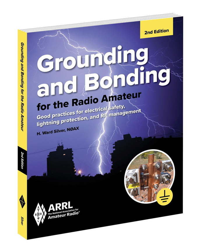
Also, additional information can be found in the ARRL’s book, “Grounding and Bonding” 2nd Edition available on Amazon and other book stores.
Prepared from Jim Hinnant’s revised “Amateur Radio Grounding Procedures” training presentation. June 2026.